Networking Notes - Part 3 (OSI model, TCP/IP model)
---------------------------------------------------------------------------------------------------------------
Useful : 1] Click
PDU (Protocol Data Unit)
In telecommunications, a protocol data unit (PDU) is a single unit of information transmitted among peer entities of a computer network. A PDU is composed of protocol-specific control information and user data.
In OSI model each layer uses a different PDU to communicate and exchange information, which can only be read by the peer layer on the receiving device and is then handed over to next upper layer after stripping.
NOTE : The PDU defines the state of the data as it moves from one layer to the next.
The protocol data unit changes between the seven different layers. The resulting information that is transferred from the application layer to the physical layer (and vice versa) is not altered, but the data undergoes a transformation in the process.
How PDU changes in OSI model ?
When a sender's data travels down the stack of layers,each layer of the OSI model encapsulates that data by adding a 'header' or sometimes a 'trailer' to data.

Here's what happens on Sender's Side :
- Application & Presentation Layer - As data moves from Application layer to Presentation layer it is compressed or encocoded to a standard format, sometimes data is encrypted.
- Session Layer - After data is converted to standard format it moves down to session layer where a Session Id is attached to the data.
NOTE : Uptil this point the data is still one whole block of data. Encapsulated data is called by different names as it travels down lower layers. These names are called PDU (protocol data unit).
- Transport layer - At the transport layer, data is broken down into smaller blocks. Each block is added with a header which contains destination port,source port,sequence number and other information. All together a new data package is created which is called 'Segment' (If TCP is used) or 'Datagram' (If UDP is used).
- Network layer - As a segment travels down to network layer a new IP header is added to each segment or datagram. IP headers contain destination IP address,source IP address and other information. A new PDU is called 'IP packet' is then created at the network layer.
- Data link layer - As the IP packets move to data link layer, a new header and a trailer (at the end of packet) is added to the IP packets. A new PDU called a 'Frame' is built. Frame header contains destination MAC address,source MAC address and other control information. while the Frame trailer marks the end of the frame and is also used for error checking.
- Physical layer - When the Frame reaches physical layer, it is translated into an appropriate signal suitable for transmission,it can be electrical,radio wave or light. Basically the Frame is converted into some kind of signal that represents a series of 1's and 0's,that's why at the physical layer we often call it as 'Bits'. The NIC (network interface card) then prepares and sends those signals through the transmission media.
NOTE : The above mentioned processes all take place on the sender's side, on the receiving end all the processed are repeated but in reverse order.

Here's what happens on Receiver's Side :
- Physical layer - The physical layer receives the bits through transmission medium and it interprets them into Frames, then transfer them to data-link layer.
- Data link layer - At this layer the header and trailer of Frame are checked. If the MAC address is matched and no error is found, the Frame is discarded and the IP packet is pulled out and delivered up to the Network layer.
- Network layer - At this layer the IP header is examined and if the IP address is matched, the Segment is pulled out from IP packet and IP packet is discarded,the segment is passed to Transport layer.
- Transport layer - At this layer the segment header is examined and the Port number is looked up and the segment is moved to the appropriate application specified by the port number.
- Session layer & Representation Layer - At this point the Session ID is used,any decompression or de-encryption algorithm is applied and data is restored back to its original format which is then presented to the Application layer.
In summary data encapsulation is about creating and wrapping user's data with control information layer by layer, and their by changing the state of data at each layer.
---------------------------------------------------------------------------------------------------------------
OSI Model (Open Systems Interconnection)
The OSI Model (Open Systems Interconnection Model) is a conceptual framework used to describe the functions of a networking system,developed in 1984 by ISO. It describes how information from a software application in one computer moves through a physical medium to the software application in another computer.
The modern Internet is not based on OSI, but on the simpler TCP/IP model. However, the OSI 7-layer model is still widely used, as it helps visualize and communicate how networks operate, and helps isolate and troubleshoot networking problems.
Much like a car is composed of independent functions which combine to accomplish the end goal of moving the car forward, OSI model is a set of seven independent functions or layers which combine to accomplish the end-goal of Computer to Computer communication.
NOTE : The OSI model is just a conceptual model,it is not something that's Implemented inside your system. It is set of layers, protocols or guidelines that govern the network. Whenever a network communication is established, it follows the guidelines of OSI model. Eg - TCP/IP model is based on OSI model and can be considered an Implementation of OSI model.

The OSI model is divided into seven different layers, each of which fulfills a very specific function. When combined together, each function contributes to enables full computer to computer data communication.

NOTE : The layers in Image follow a Top-to-Bottom approach describing the layer closest to the user (Application layer) at the Top and layer farthest to the user at Bottom. At Sender end the Application Layer is first layer but at Receiver end the Application layer is the last layer.
The Upper 3 layers (layer 5, 6, 7) of the OSI model mainly deals with the software and lower 3 layer (layer 1, 2, 3) deals with hardware. Intermediate layer (layer 4) deals with both hardware and software. The layer of OSI model are also categorized as upper and lower layers as shown below.

Each layer in OSI model uses different types of Protocols,Devices and PDU to transmit data to layer below or above them. You can think of each layer being "Package of Network Protocols".

1] Application Layer
The Application layer is closest to the user and it interacts with an application program. The application layer provides services for an application program to ensure that effective communication with another application program on a network is possible.
The Application layer should not be thought of as an application program. The application layer is mainly used by network applications like Chrome,Skype etc. It's an abstraction layer service that masks the rest of the application from the transmission process.
It provides protocols that allow software to send and receive information and present meaningful data to users. For example, the web browser is an application program which uses application layer,it does'nt reside in the application layer but it uses the Protocols from application layers like HTTP,SMTP,FTP etc. The application layer basically provides different protocols to the user for various applications.
2] Presentation Layer
The presentation layer takes any data transmitted by the application layer and prepares it for transmission over the next layer. The presentation layer transforms data into the form that the application accepts. On the sender's end this layer Formats,Compress and Encrypts data to be sent across a network,then at receiver's end the data is again formatted and decrypted to its original form.
The presentation layer is also called as Syntax/Translation layer since it is responsible for maintaining the proper syntax of the data which it either receives or transmits to other layer. The SSL (secure socket layer) protocol is commonly used during Encryption and Decryption of data. The presentation layer is responsible for interoperability between encoding methods as different computers use different encoding methods. It translates data between the formats the network requires and the format of the computer.
The presentation layer is primarily concerned with the format of the data. Data and text can be formatted as ASCII files, as EBCDIC files or can even be Encrypted. Sound may become a Midi file. Video files can be formatted as MPEG video files or QuickTime files. Graphics and visual images can be formatted as PICT, TIFF, JPEG, or even GIF files.
The function of Presentation Layers :
- Character code translation from ASCII to EBCDIC.
- Data compression: Allows to reduce the number of bits that needs to be transmitted on the network.
- Data encryption: Helps you to encrypt data for security purposes — for example, password encryption.
- It provides a user interface and support for services like email and file transfer.
3] Session Layer
The session layer creates communication channels, called sessions, between devices. It is responsible for opening sessions, ensuring they remain open and functional while data is being transferred, and closing them when communication ends. The session layer can also set checkpoints during a data transfer,if the session is interrupted, devices can resume data transfer from the last checkpoint.
The session layer is also responsible for Authentication & Authorisation at the server's end to establish a connection. Example of session - When you request for a website,the browser creates a network session with the web server.
Important
The Session, Presentation, and Application layers of the OSI model handle the final steps before the data transferred through the network (facilitated by layers 1-4) is displayed to the end user. From a purely Network Engineering perspective, the distinction between Layers 5, 6, and 7 is not particularly significant. In fact, there is another popular Internet communication model known as the TCP/IP model, which groups these three layers into one single encompassing layer.
A Web browser can perform all the functions of Application,Presentation and Session layer.
4] Transport Layer
The basic function of the Transport layer is to accept data from the layer above, split it up into smaller units, pass these data units to the Network layer, and ensure that all the pieces arrive correctly at the other end. The transport layer (Layer 4) is responsible for delivery of data from an application program on the source device to a similar application program on the destination device.
NOTE : It’s an end-to-end or process-to-process communication layer. The transport layer ensures the communication between the process of a host to the process of another host. For the process to process communication, the transport layer uses a "port number" assigned to each process uniquely. It’s important to note that the use of ports is crucial in the transport layer. In general, a single IP address is assigned to a host. A sender host sends the data to the receiver host with a port number. Furthermore, the receiver host can identify the port and will route the data to a specific process.
It controls the reliability of communication by performing the following functions :
- Segmentation & Reassembling
- Service Point Addressing
- Flow control
- Error control
Segmentation & Reassembling
When data arrives at the transport layer from the upper layers, it is taken then divided into segments. That is why data at this layer is called segments rather than data. Thus, The PDU (Protocol Data Unit) of this layer is segment(s).
Segmentation is crucial for effective transmission of data. For Example,Computer A is sending a video, whose size is 100MB, to computer B. During the transmission, the internet went off and the whole video has not been received,this is problematic. For this reason, data (videos, pictures, audios, texts) is divided into segments. If the video is split into pieces, we will at least guarantee that part of the video/data is received after the cut of the internet, then the transmission can later be resumed.
NOTE : Each segment of the data is assigned 3 things (source & destination port address, sequence number). A sequence number helps during reassembling and during Loss control,whereas Port numbers help in service-point delivery.
Reassembly is another function of transport layer.After data is segmented and sent to the destination machine, this layer reassembles the segments in the correct order even if the segments are in an disorderly way. Segments may take different routes in order to reach the destination.
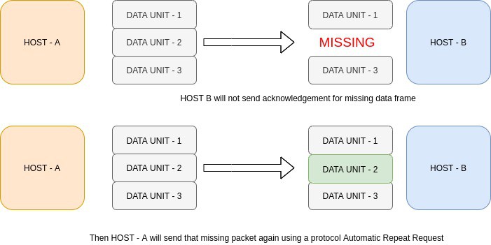
The transport layer also has a "Loss Control" mechanism which ensures that all the segments of a transmission arrive at the destination, not some of them. On the sending end, all the segments of transmission are given sequence numbers by a transport layer. These sequence numbers allow the receiver's transport layer to identify the missing segments and request them again.
Service Point Addressing
At any given time on a user’s computer there might be an Internet browser open, while music is being streamed, while a messenger or chat app is running. Each of these applications are sending and receiving data from the Internet, and all that data is arriving in the form of 1’s and 0’s on to that computer’s NIC.
The transport layer makes sure that each segment is passed to the correct process in the computer. Transport Layer header includes service point address or port address. This layer gets the data to the correct process on the computer.
In order to deliver the data or segments to the correct process, Transport Layer header includes a type fo address called 'service point address' or Port address. By specifying this address the transport layer makes sures the data gets to the correct process on the computer.
Flow Control
In Flow control the transport layer controls the amount of data being transmitted. It basically prevents overwhelming or underwhelming of data on receiver's end.
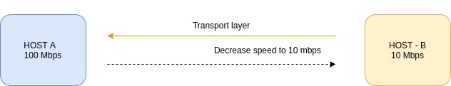
For example,If you are downloading a file from a server and the server is sending data at 50MBps but your device can only process data at 10MBps then the transport layer on receiver's end sends a signal to the sender's transport layer to lower down transmission speed. It can also be vice-versa where the receiver's processing speed is more than sender's transmission speed in which case sender needs to increase transmission speed.
Error Control
During transmission, digital signals suffer from noise that can introduce errors in the binary bits travelling from sender to receiver. That means a 0 bit may change to 1 or a 1 bit may change to 0. Whenever a message is transmitted, it may get scrambled by noise or data may get corrupted. To avoid this, we use error-detecting codes which are additional data added to a given digital message to help us detect if any error has occurred during transmission of the message.
5] Network Layer
The network layer has two main functions. One is breaking up segments into network packets, and reassembling the packets on the receiving end. The other is routing packets by discovering the best path across a physical network. The network layer uses network addresses (typically IP addresses) to route packets to a destination node.
It’s responsible for host-to-host delivery of packets across multiple networks. Switches and routers are used in this layer. The network layer is implemented on networking devices. It uses the destination host and the source host’s logical address (IP address) to send the data. An IP address is a combination of the network address and host machine address.
Sending data from one process to another process is accomplished by the transport layer. In order to send data from one process to another, first we need to send the data to the destination host. In order to achieve this, we use the network layer as both of the processes are in different networks.
The network layer receives the data to be transmitted from its upper layer along with some other pieces of information such as the length of data, ID of the protocol used, type of service logical address of the destination, and the logical address of the destination computer. The network layer encapsulates this data by adding the header to this data and forms a datagram.
Just like transport layer,Network layer also provides the following services :
- Fragmentation
- Routing
- Flow control
- Error control
Fragmentation
Each network has its maximum transmission unit (MTU). It dictates the maximum size of the data that can be transmitted through it. Data packets of size greater than MTU can not be transmitted through the network. The source computer is even not aware of the path the packet will take to reach the destination. So, it is unable to decide how small each data fragment must be.Routing
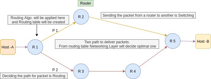
Routing is a process that is performed by layer 3 (or network layer) devices in order to deliver the packet by choosing an optimal path from one network to another. It’ll make a routing table for the shortest possible path from source to destination. Also, it switches the packets from different networking devices. When the packets reach their destination host, then the transport layer will route the packets to their respective processes using their port number.
6] Data Link Layer
The data link layer is the closest to the physical hardware layer. The data link layer receives data packets from the network layer. It provides the building blocks for communication across variety of physical media. When a packet or message reaches to a network, it is the responsibility of Data Link Layer to transmit it to the Host using its MAC address. Two types of Data Link layer devices are commonly used on networks: bridges and switches.
The Data Link layer of the OSI model is responsible for interfacing with the Physical layer. Effectively, Layer 2 is responsible for putting 1’s and 0’s on the wire, and pulling 1’s and 0’s from the wire.The Network Interface Card (NIC) that you plug your Ethernet wire into handles the Layer 2 functionality. It receives signals from the wire, and transmits signals on to the wire.
Your WiFi NIC works the same way, receiving and transmitting radio waves which are then interpreted as a series of 1’s and 0’s. Layer 2 will then group together those 1’s and 0’s into chunks known as Frames. There is an addressing system that exists at Layer 2 known as the Media Access Control address, or MAC address. The overarching function of the Data Link layer is to deliver packets from one NIC to another. Or to put it another way, the role of Layer 2 is to deliver packets from 'hop to hop'.
Some of the functions of Data link layer are as followed :
- Framing
- Physical Addressing
- Flow Control
- Error Control
- Access Control
Framing
Data-link layer takes the packets from the Network Layer and encapsulates them into frames. If the frame size becomes too large, then the packet may be divided into small sized frames. At receiver’ end, data link layer picks up signals from hardware and assembles them into frames.

A frame is a simple container for a single network packet,it consists of a header followed by a packet. The header consists of control information whose role is to guide the the whole frame to its correct destination.
Physical Addressing
In order to communicate or transfer the data from one computer to another computer we need some address. After creating frames, the Data link layer adds physical addresses (MAC address) of the sender and/or receiver in the header of each frame,which helps to transfer these frames to the Physical layer.
SubLayers of DLL
The data link layer actually consists of two sublayers :
- Media Access Control (MAC) sublayer
- Logical Link Control (LLC) sublayer
Media Access Control (LLC) : This layer controls who can access the transmission media at any one time. The packet obtains from the Network layer is further divided into frames depending on the frame size of NIC(Network Interface Card). DLL also encases Sender's and Receiver's MAC address in the header.
The basic function of MAC is to provide an addressing mechanism and channel access so that each node available on a network can communicate with other nodes available on the same or other networks.
7] Physical Layer
Physical layer is the lowest layer of the OSI reference model. It is responsible for the transfer of bits ,the 1’s and 0’s which make up all computer code. This layer defines the hardware equipment, cabling, wiring, frequencies, pulses used to represent binary signals etc.
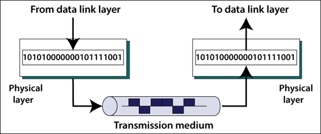
Physical layer provides its services to Data-link layer. Data-link layer hands over frames to physical layer. Physical layer converts them to electrical pulses, which represent binary data.The binary data is then sent over the wired or wireless media.
NOTE : There are no specific protocols that are used in this layer as functionality of the physical layer varies from network-to-network.
This layer represents the physical medium which is carrying the traffic between two nodes. An example would be your Ethernet cable or Serial Cable. But don’t get too caught up on the word “Physical” — this layer was named in the 1970s, long before wireless communication in networking was a concept. As such, WiFi, despite it not having a physical, tangible presence, is also considered a Layer 1 protocol. Simply put, Layer 1 is anything that carries 1’s and 0’s between two nodes.
The actual format of the data on the “wire” can vary with each medium. In the case of Ethernet, bits are transferred in the form of electric pulses. In the case of Wifi, bits are transferred in the form of radio waves. In the case of Fiber, bits are transferred in the form of pulses of light.
---------------------------------------------------------------------------------------------------------------
TCP/IP Model
TCP/IP model is another reference model just like OSI model. The TCP/IP model is older than OSI model and was defined before the advent of internet. Although both the TCP/IP and OSI models transport data, the ways they send it are slightly different, which is sometimes why TCP/IP is used instead of OSI. The TCP/IP is the implementation of the OSI Model.
 |
Old version of TCP/IP model |
NOTE : The 'Network layer' in TCP/IP model is also called 'Internet Layer'.
NOTE : The OSI model is a general conceptual model which describes how computer systems which are open for an interconnection can be connected to each other to transmit data. On the other hand the TCP/IP mode describes how a computer system can connect to the Internet and transfer data over it to another system.
In the early days, the TCP/IP reference model had 4 layers, as described below :

These layers are much similar to the layers of the OSI model. The Application layer in the TCP/IP model has approximately the same functionality as the upper 3 layers (Application, Presentation, and Session layer) of the OSI model. Also, the Internet layer acts as the Network layer, and the Network Access layer acts as the lower 2 layers (Physical and Data-Link layer) of the OSI model.
Nowadays, we generally use a 4-layer TCP/IP model, as shown below.

In the latest TCP/IP model, the Physical and Data-Link layer acts as the Network Access layer of the previously used older TCP/IP model.
Just like OSI model each layer in TCP/IP model has its own function and set of protocols to perform those functions. Each layer takes data from its previous layer,perform some transformation or add headers,and sends it to the next layer.

Application Layer
The Application layer in the TCP/IP model is equivalent to the upper 3 layers (Application, Physical, and Session Layer) of the OSI model. It mainly provides services to the end-users to work over the network. For Example, file transfer, web browsing, etc. This layer uses all the higher-level protocols like HTTP, HTTPS, FTP, NFS, DHCP, FMTP, SNMP, SMTP, Telnet, etc.
It is the Top most layer of the model. It's main functions are to take data from user, translate into standard format, compress or decompress data, perform encryption or decryption on data, create a session between the source and destination systems etc. Basically it performs all the actions of the first 3 layers of the OSI model.
Transport Layer
The Transport layer is the fourth layer of the TCP/IP model. It deals with data in the form of data segments. It mainly performs segmentation of the data received from the upper layers. It performs the same functions as the Transport layer in OSI reference model.
The transport layer works on two determined communication modes: Connection oriented (like TCP) and connectionless (liek UDP). This layer transmits data from source to destination node.
At the transport layer, data is broken down into smaller blocks. Each block is added with a header which contains destination port,source port,sequence number and other information. All together a new data package is created which is called 'Segment' (If TCP is used) or 'Datagram' (If UDP is used).
Internet/Network Layer
The Internet layer of the TCP/IP model is approximately the same as the Network layer of the OSI model. It deals with data in the form of datagrams or data packets. This layer mainly performs the logical addressing of the data packets by adding the IP(Internet Protocol) address to it. The IP addressing can be done either by using the Internet Protocol Version 4(IPv4) or Internet Protocol Version 6(IPv6). The Internet layer also performs routing of data packets using the IP addresses.
As a segment travels down to network layer a new IP header is added to each segment or datagram. IP headers contain destination IP address,source IP address and other information. A new PDU is called 'IP packet' is then created at the network layer.
The protocols that are used in the Internet layer are IP(Internet Protocol), ICMP(Internet Control Message Protocol), IGMP(Internet Group Management Protocol), ARP(Address Resolution Protocol), RARP(Reverse Address Resolution Protocol), etc.
Data link Layer
The Data-Link Layer is the second layer of the TCP/IP layer. It deals with data in the form of data frames. It mainly performs the data framing in which, it adds some header information to the data packets for the successful delivery of data packets to correct destinations. For this, it performs physical addressing of the data packets by adding the source and the destination address to it.
It also facilitates the flow and error control of the data frames. The flow of the data can be controlled through the data rate. Also, the errors in the data transmission and faulty data frames can be detected and retransmitted using the checksum bits in the header information.
As the IP packets move to data link layer, a new header and a trailer (at the end of packet) is added to the IP packets. A new PDU called a 'Frame' is built. Frame header contains destination MAC address,source MAC address and other control information. while the Frame trailer marks the end of the frame and is also used for error checking.
Physical Layer
The Physical Layer is the lowest layer of the TCP/IP model. It deals with data in the form of bits. This layer mainly handles the host to host communication in the network. It defines the transmission medium and mode of communication between two devices. The medium can be wired or wireless.
There are no specific protocols that are used in this layer. The functionality of the physical layer varies from network-to-network. When the Frame reaches physical layer, it is translated into an appropriate signal suitable for transmission,it can be electrical,radio wave or light. Basically the Frame is converted into some kind of signal that represents a series of 1's and 0's,that's why at the physical layer we often call it as 'Bits'. The NIC (network interface card) then prepares and sends those signals through the transmission media.
---------------------------------------------------------------------------------------------------------------


Comments
Post a Comment